
[CA4]
4.1. Introduction
Performance of a computer:
- instruction count (determined by the ISA and the compiler.)
- clock cycle time
- clock cycles per instruction (CPI).
Implementation of the processor determines both the clock cycle time and the number of CPI.
Construct the datapath and control unit for two different implementations of the MIPS instruction set.
- A simplified version
- A more realistic pipelined version.
‘key question’ in creating a datapath and designing the control: Examine implementations of…
- Memory reference instructions: lw, sw
- Arithmetic-logical instructions: add, sub, AND, OR, and slt
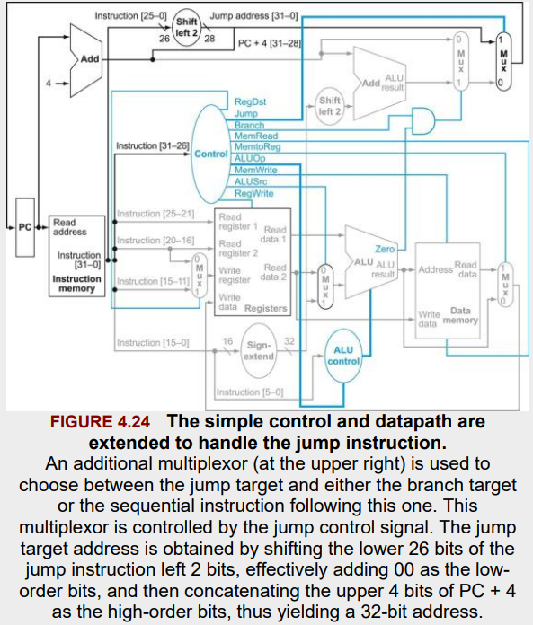
- Control transfer: beq, j
4.2. Logic Design Conventions
terms
- combinational & sequential(=state) element: An operational element such as an AND gate or an ALU. / A memory element. e.g. register or a memory.
- clocking methodology: The approach used to determine when data is valid and stable relative to the clock.
- edge-triggered clocking: A clocking scheme in which all state changes occur on a clock edge.
- control signal: A signal used for multiplexor selection or for directing the operation of a functional unit; contrasts with a data signal, which contains information that is operated on by a functional unit.
- asserted / deasserted : The signal is logically high or true / low or false.
from Appendix B.
B.2. Gates, Truth Tables, and Logical Equations
- asserted signal: A signal that is logically true, or 1.
- deasserted signal: A signal that is (logically) false, or 0.
- combinational logic: A logic system whose blocks do not contain memory and hence comput the same output given the same input.
- sequential logic: A group of logic elements that contain memory and hence whose value depends on the inputs as well as the currnt contents of the memory.
- gate: A device that implements basic logic functions, such as AND or OR. e.g. NOR gate, NAND gate.
B.3. Combinational Logic
- decoder: A logic block that has an n-bit input and \(2^{n}\) outputs, where only one output is asserted for each input combination. e.g. 3-to-8 decoder, 5-to-32 decoder.
- multiplexor: A logic element that chooses from among the multiple sources and steers one of those sources to its destination. (combinational!)
- selector value (=control value): The control signal that is used to select one of the input values of a multiplexor as the output of the multiplexor.
Logic Design Basics
- Information encoded in binary.
- Low voltage = 0, High Voltage = 1
- One wire per bit.
- Multi-bit data encoded on multi-wire buses.
-
- combinational element
- An operational element. (Output doesn’t depend on memory, but only on its inputs)
e.g. multiplexor, AND, OR, ALU
-
- State(sequential) element
- A memory element (output depends on both internal state(memory) and inputs)
e.g. register, memory
Combinational Elements
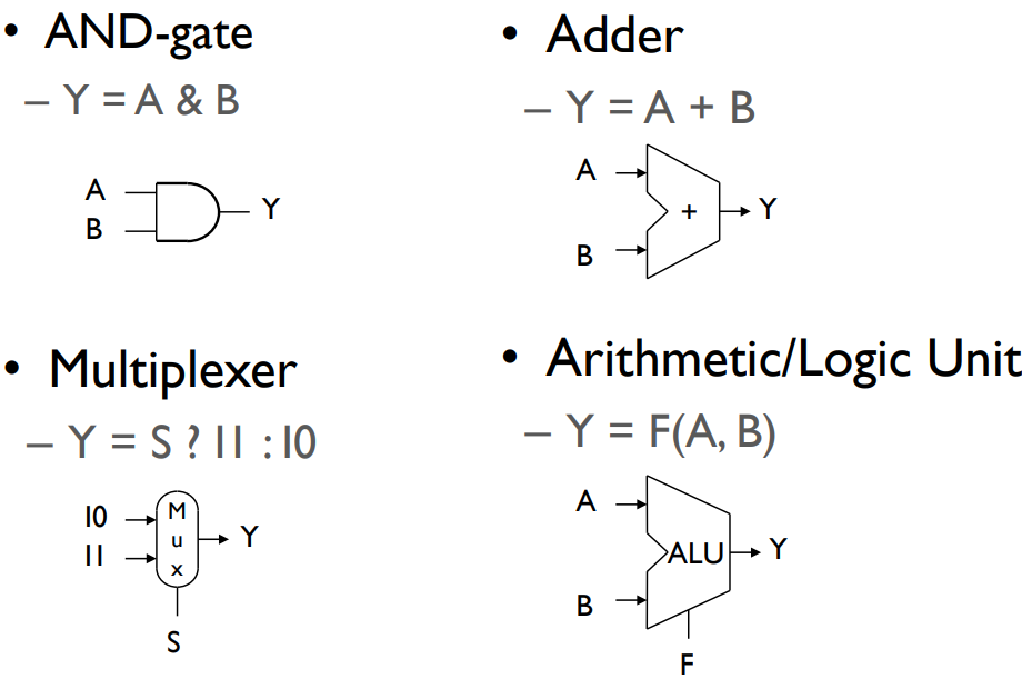
(S: signal/controller)
Sequential Elements
edge-triggered clocking: clock이 0->1로 shift 할 때 동작함.
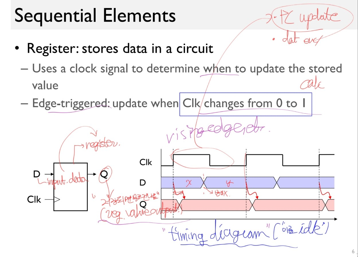
write 신호까지 줄 경우 write가 1일때라는 and 조건이 추가되기도 함.
Clocking Methodology
See the slides and paste it if you want.
edge-triggered clocking: A clocking scheme in which all state changes occur on a clock edge.
4.3. Building a Datapath
terms:
-
- datapath element
- A unit usd to operate on or hold data within a procssor. In the MIPS implementation, the datapath elements include the instruction and data memories, the register file, the ALU and adders.
-
- register file
- A state element that consists of a set of registers that can be read and written by supplying a register number to be accessed.
-
- sign-extend
- To increase the size of a data item by replicating the high-order sign bit of the original data item in the high-order bits of the larger, destination data item.
-
- branch target address
- The address specified in a branch, which becomes the new program counter (PC) if the branch is taken. In the MIPS architecture the branch target is given by the sum of the offset field of the instruction and the address of the instruction following the branch.
-
- branch taken
- A branch where the branch condition is satisfied and the PC becomes the branch target. All unconditional jumps are taken branches.
-
- branch not taken (or untaken branch)
- A branch where the branch condition is false & the PC becomes the address of the instruction that sequentially follows the branch.
-
- delayed branch
- A type of branch where the instruction immediately following the branch is always executed independent of whether the branch condition is T or F.
3 core multiplexors:
- The value written to the PC: From which of two adders? (conditional branch or from the PC+4)
- Data written to the register file: From the Mem or the ALU?
- The second operand of the ALU: From the register or th immediate field?
- Controls:
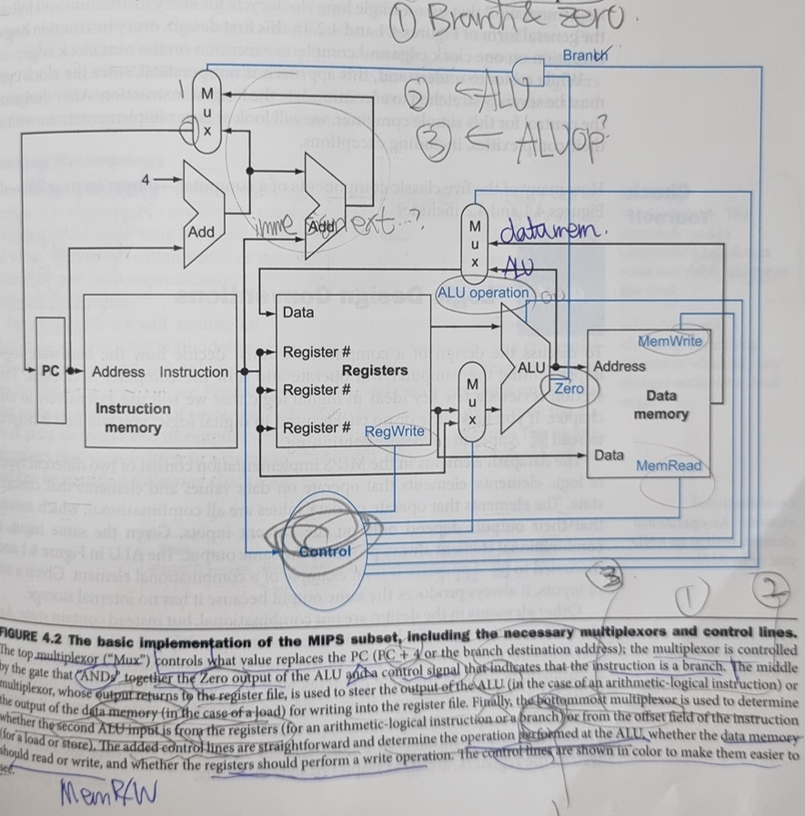
- (Branch & Zero)?arithmetic ALU:PC ALU
- (MemtoReg)?Data memory:arithmetic ALU?
- (ALUSrc)? ? : ?
그래서 몇 개 더하면 된다.
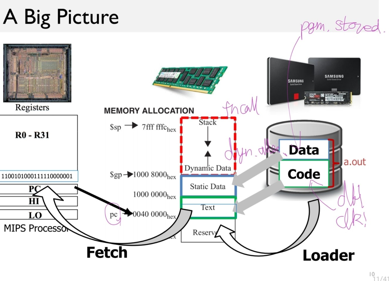
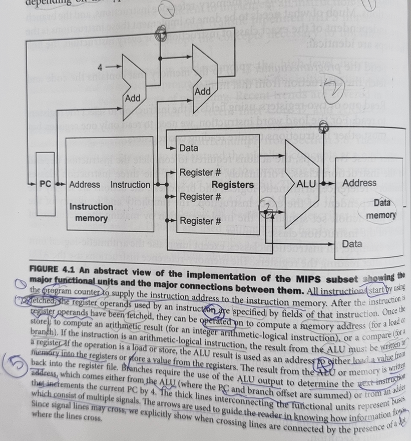
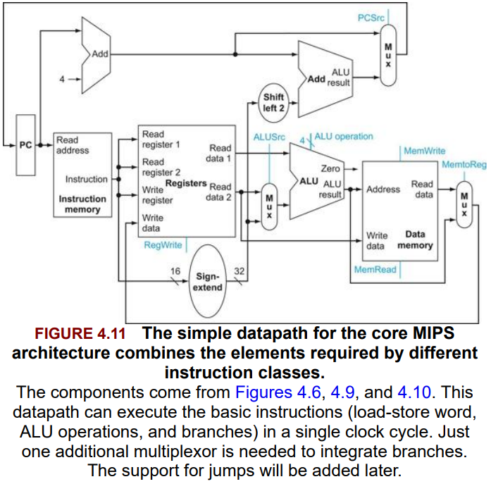
- Instruction memory, Program Counter, Adder 에서부터 시작,
- Register File로 register operand를 읽어오고, register value 받아오기 ㅇㅇ
- ALU 계산하기.
- Memory 읽고쓰기
- Write Back하기
Fig 4.5
Figure 4.9 ㅇㅇ
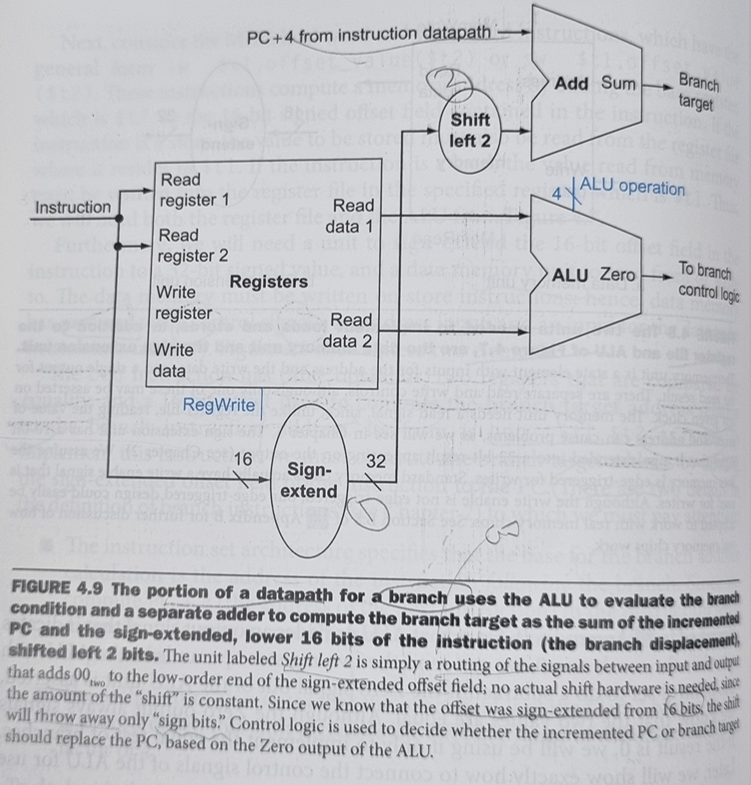
shift left 2해서 ㅇㅇ
4.4. A Simple Implementation Scheme
terms
- truth table: From logic, a representation of a logical operation by listing all the values of the inputs and then in each case showing what the resulting outputs should be.
- don’t-care term: An element of a logical function in which the output does not depend on the values of all the inputs. Don’t-care terms may be specified in different ways.
- opcode: The field that denotes the operation and format of an instruction.
- single-(/single clock) cycle implementation: An implementation in which all instructions are executed in one clock cycle. While easy to understand, it is too slow to be practical.
The ALU control lines and the corresponding function
| ALU control lines | Function |
|---|---|
| 0000 | AND |
| 0001 | OR |
| 0010 | add |
| 0110 | subtract |
| 0111 | set on less than |
| 1100 | NOR |
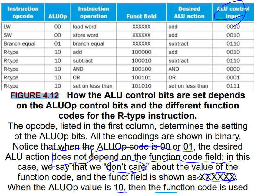
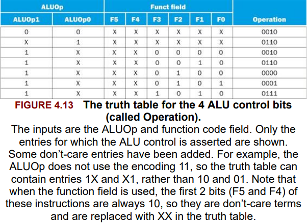
Fig 4.15
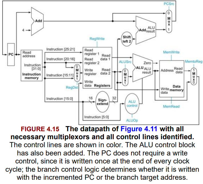
| bit# | Signal name | Effect when deasserted(0) | Effect when asserted(1) |
|---|---|---|---|
| 1 | PCSrc | The PC is replaced by the output of the adder that computes the value of PC + 4. | The PC is replaced by the output of the adder that computes the branch target. |
| 1 | MemtoReg | The value fed to the register Write data input comes from the ALU. | The value fed to the register write data input are replaced by the value on the (memory) Write data input. |
| 1 | MemWrite | None | Data memory contents designated by the address input are replaced by the value on the Write data input. |
| 1 | MemRead | None | Data memory contents designated by the address input are put on the Read data output. |
| 1 | RegWrite | None | The register on the Write register input is written with the value on the Write data input. |
| 1 | RegDst | The register destination number for the Write register comes from the rt field (bits 20:16). | The register destination number for the Write register comes from the rd field (bits 15:11). |
| 2 | ALUOp | Refer to figure 4.13. | |
| 1 | ALUSrc | 2nd operand of the ALU becomes the second register file (Read data 2). | 2nd operand of the ALU becomes the 32bit sign-extended immediate field(lower 16 bits of the instruction). |
(NO RegRead as we must always read the register or writting control of the PC.)
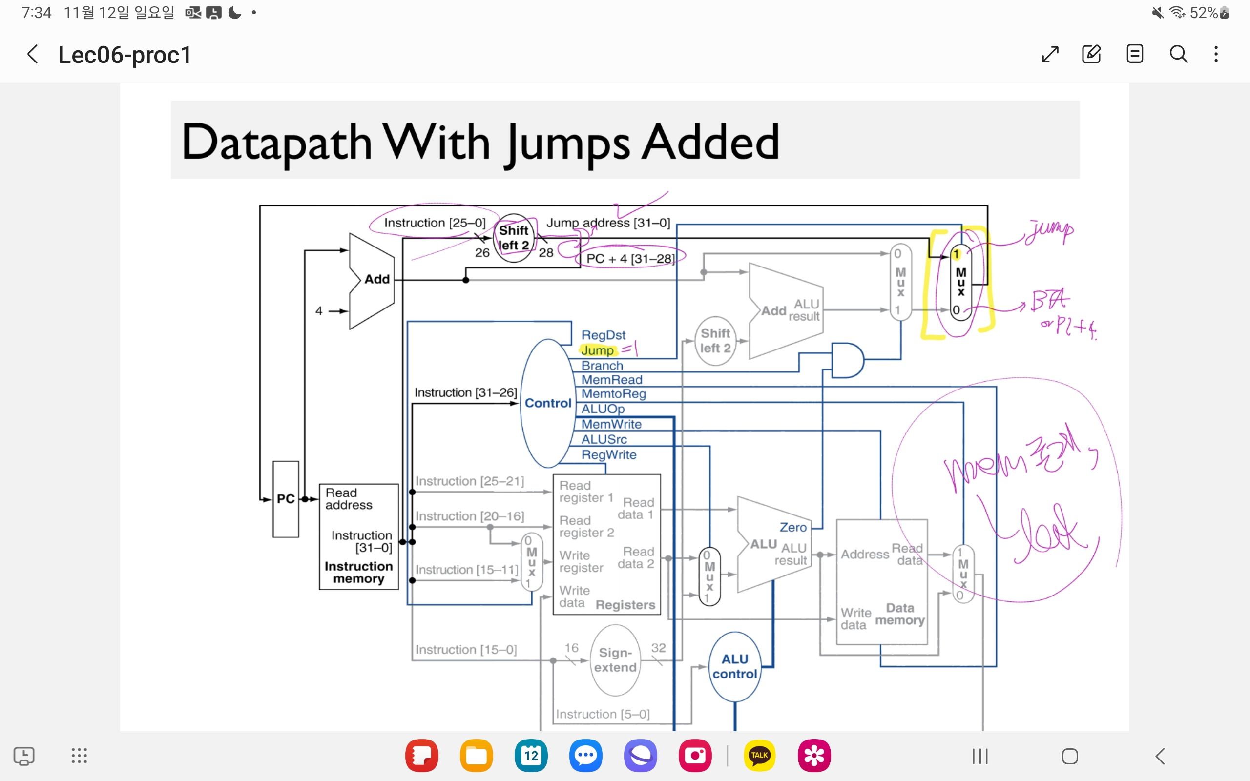
Then, now we replace the PCSrc with Branch.
1 bit, and is ‘AND’ed with the Zero from the ALU to determine the PCSrc. We no longer discuss the PCSrc as a signal from the control as it is now known as a derived signal.
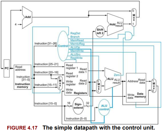
Fig 4.18
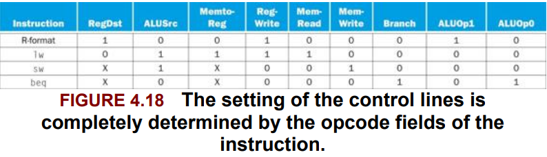
Fig 4.24
Clock blarg
YesYes See the print and the figure of mine and Let’s revise the figure.
신호값들도 있음 ㅇㅇ
Lec06-proc1 이따 보기! + 위 그림을 diagram으로 ㄱㄱ
4.5. A Multicycle Implementation (Later)
multicycle implementation?
4.6. An Overview of Pipelining
terms
- pipelining: An implementation technique in which multiple instructions are overlapped in execution, much like an assembly line.
자 laundry를 pipeline 돌려본다고 생각하자.
non-pipelined approach:
- Place one dirty load of clothes in the washer.
- When the washer is finished, plac th wed load in the dryer.
- When the dryer is finished, place the dry load on a table and fold.
- When folding is finished, ask your roommate to put the clothes away.
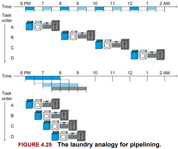
이게 non-pipelined approach이고,
PPL 돌리면 이렇게 돌릴 수 있다:
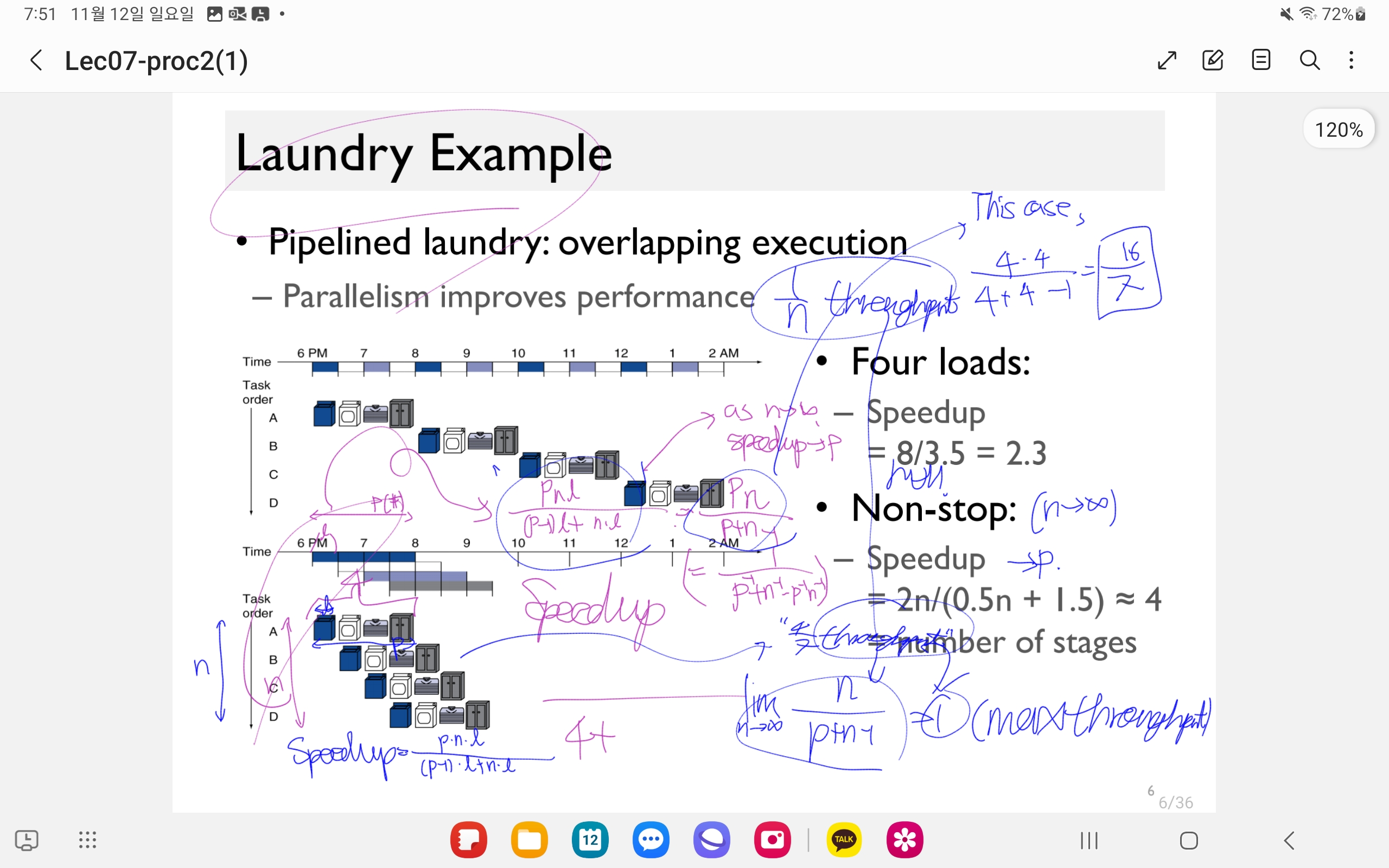
Laundry Example ㅇㅇ
이 경우,
Instruction 하나를 처리하는데 드는 시간, latency는 더 적지 않지만,
단위클럭동안 처리되는 instruction 수인 throughput은 증가한다. (?)
(or bandwidth 증가)
‘throughput: 1 cycle당 처리하는 그거 개수.’
Balanced될수록 speedup 증가한다. ㅇㅇ
- 왜하냐
- 성능 얼마 증가?
- balanced가 뭔 의미?
- structural hazard: When a planned instruction cannot execute in the proper clock cycle because the hardware does not support the combination of instructions that are set to execute.
- data hazard (= pipline data hazard): When a planned instruction cannot excute in the proper clock cycle because data that is needed to execute the instruction is not yet available.
- forwarding (= bypassing): A method of resolving a data hazard by retrieving the missing data element from internal buffers rather than waiting for it to arrive from programmer-visible registers or memory.
- load-use data hazard: A specific form of data hazard in which th data being loaded by a load instrcution has not yet become available when it is neded by anothr instruction
- pipeline stall(=bubble): A stall initiated in order to resolve a hazard.
- control hazard (= branch hazard): When the proper instruction cannot execute in the proper pipeline clock cycle because the instruction that was fetched is not the one that is needed; that is, the flow of instruction addresses is not what the pipeline expected.
- branch prediction: A method of resolving a branch hazard that assumes a given outcome for the branch and proceeds from that assumption rather than waiting to ascertain th actual outcome.
Hazards
- Structure Hazards A required resource is busy.
nyum nyum a bit later.
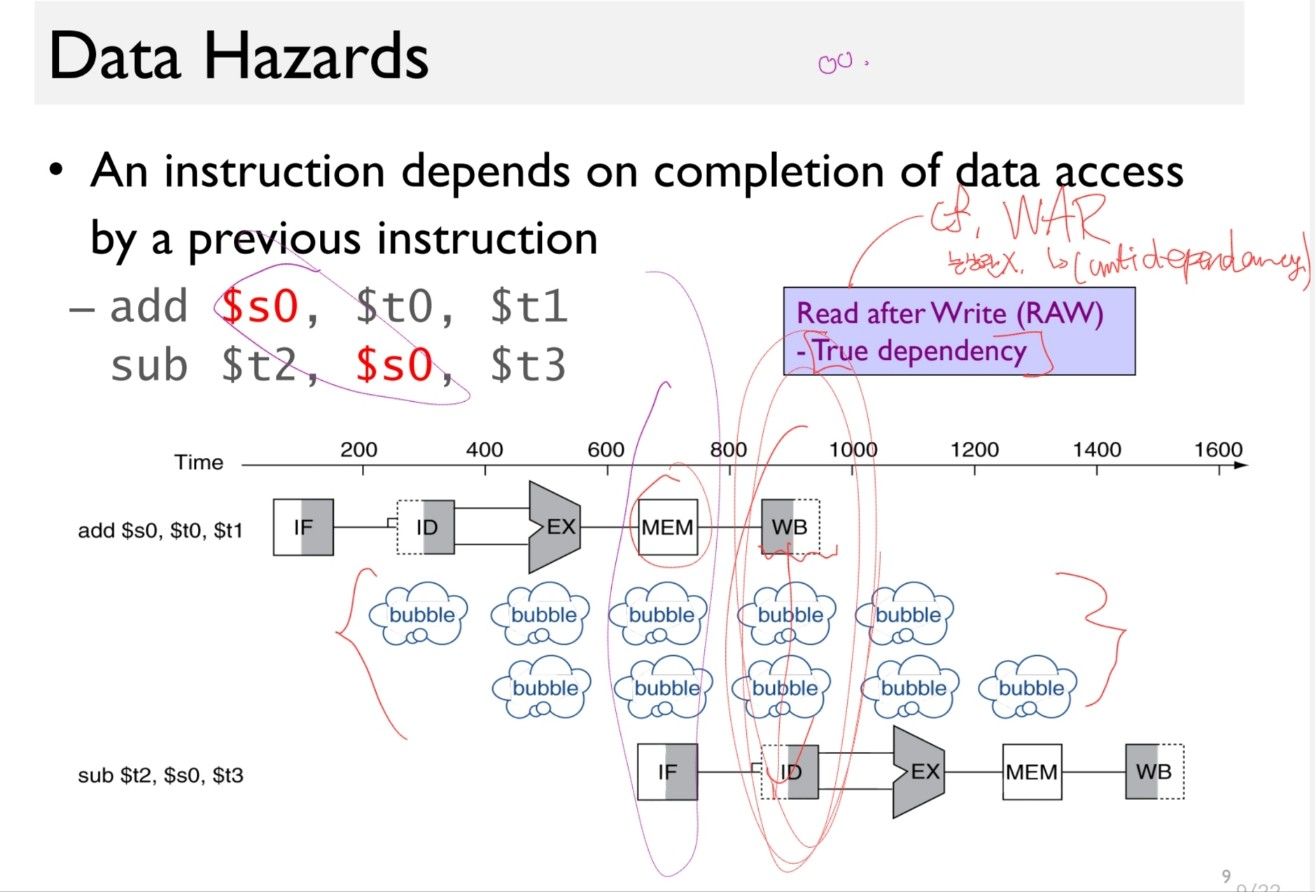
- Data Hazard Need to wait for previous instruction to complete its data read/write.
When a planned instruction cannot xcute in the proper clock cycle because the needed data to execute the instruction is not yet available.
How to solve?
- Naive approach: The SW(Compiler) stalls the pipeline.
add $s0, $t0, $t1
sub $t2, $s0, $t3
Disadvantages: We have to waste 3 cycles.(as the WB must be done before ID of the next instruction) This happenes too often.
- Better Solution: The Hardware forwards the data.
- Add an extra hardware to retrieve the missing item early from the internal resources.
i.e. forward the data sending path from the first instruction’s EX to the next instruction’s ID. => get $s0 with only 1-cycle stall!
- forwarding/bypassing
- A method of resolving a data hazard by retrieving the missing data element from internal buffers rather than waiting for it to arrive from programmer-visible registers or memory.
Solution?
ㅇㅇ From the Lec08-proc3(1) 표시 안 된 부분 or 그 전 prints.
- Control Hazard Deciding on control action depends on previous instruction.
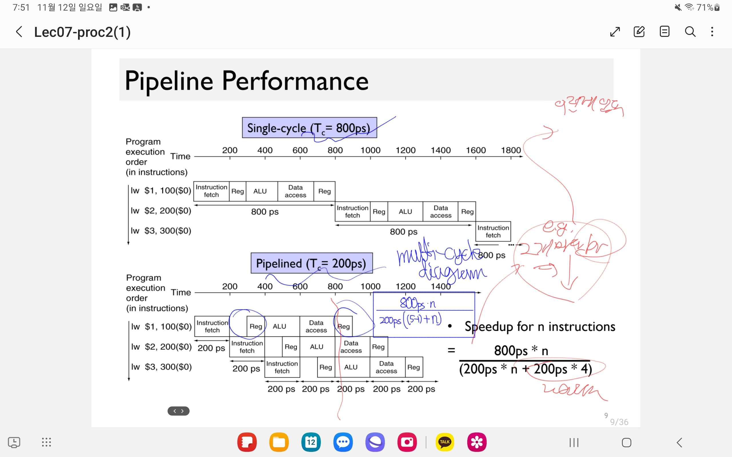
When does the Multi-cycle datapath perform better than single-cycles?
benefit : one instruction involves many “stages”. (e.g. 30 stages => better performance.)
In this case, beneficial.
e.g. Single-cycle : T_c = 800ps, Pipelined => T_c = 200ps
speedup for n instructions
\[nyum\]Imbalanced time consumption of execution =>
spedup = throughput (*2, not *5).
4.7. Pipelined Datapath and Control
terms:
- latency (pipeline): The number of stages in a pipeline or the number of stages between two instructions during execution.
5 Steps:
- IF : Instruction fetch from memory
- ID : Instruction decode & register read
- EX : Execute operation or calculate address
- MEM : Access memory operand
- WB : Write result back to register
| Instr | IF | ID | ALU op | Mem | RegWrite(WB) | Total Time |
|---|---|---|---|---|---|---|
| lw | 200 | 100 | 200 | 200 | 100 | 800 |
| sw | 200 | 100 | 200 | 200 | 700 | |
| R-format | 200 | 100 | 200 | 200 | 100 | 800 |
| lw | 200 | 100 | 200 | 200 | 100 | 800 |
(4.5. : need additional register in PP)
Structural Hazard - from 4.6
Structural Hazard:
메모리 1개가지고 instruction이랑 data 둘다 쓰게 된다.
Conflict for use of a resource: In MIPS ppl with a single memory,
- Load/Store requires a data access.
- Instruction fetch would have to stall for that cycle, causing a pipeline “bubble”
=> Seperate instruction/data memories or caches. 분리해서 쓰라는 개념 ㅇㅇ
4.8. Data Hazards: Forwarding versus Stalling
terms:
- nop: An instruction that does no operation to change state.
Performing the instructions, we write the data on registers or memories in two stages:
- WB
- MEM.
However, we may need the data written there by the following instructions, which is not updated yet.
This is the case of ‘Read After Write’(RAW) dependency.
Then, how should we solve this issue?
In cases of the WB, writing on the register, not being updated before the execution of the subsequent ID, we call this data hazard.
We divide two cases of data hazards:
- R-type data hazard
- Load data hazard
4.8.1. R-type data hazard
Let’s see the below assembly code.
add $s0, $t0, $t1
sub $t2, $s0, $t3
The $s0 in the sub instruction is accessed right after writing on it by the previous add instruction.
A Naive solution: Bubble * 3!
A better solution is to forward the data.
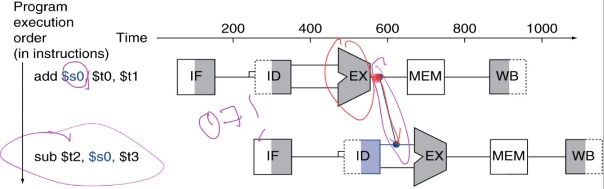
forward the data sending path from the first instruction’s EX to the next instruction’s ID. => get $s0 with only 1-cycle stall!
- forwarding/bypassing
- A method of resolving a data hazard by retrieving the missing data element from internal buffers rather than waiting for it to arrive from programmer-visible registers or memory.
i.e. we use the result as soon as it is computed.
- Don’t wait for it to be stord in a register.
- Requires extra connections in the datapath.
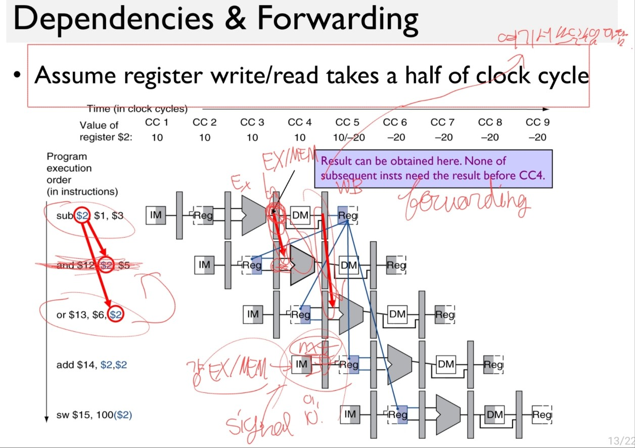
When to forward? Let’s see.
Detection
When the register value is written (via R-type instruction) and then accessed by 2 subsequent instructions, is the condition we want to get.
Note that
- under the assumption that register write/read takes only a half of the clock cycle,
We don't have to consider the RAW dependencies of 3rd or more of next instructions. - We may forward the data
- from the previous instruction’s EX/MEM reg to start of the next cycle of next instruction’s EX operation,
- from the MEM/WB reg to 2nd next instruction’s EX operation at 2nd next cycle.
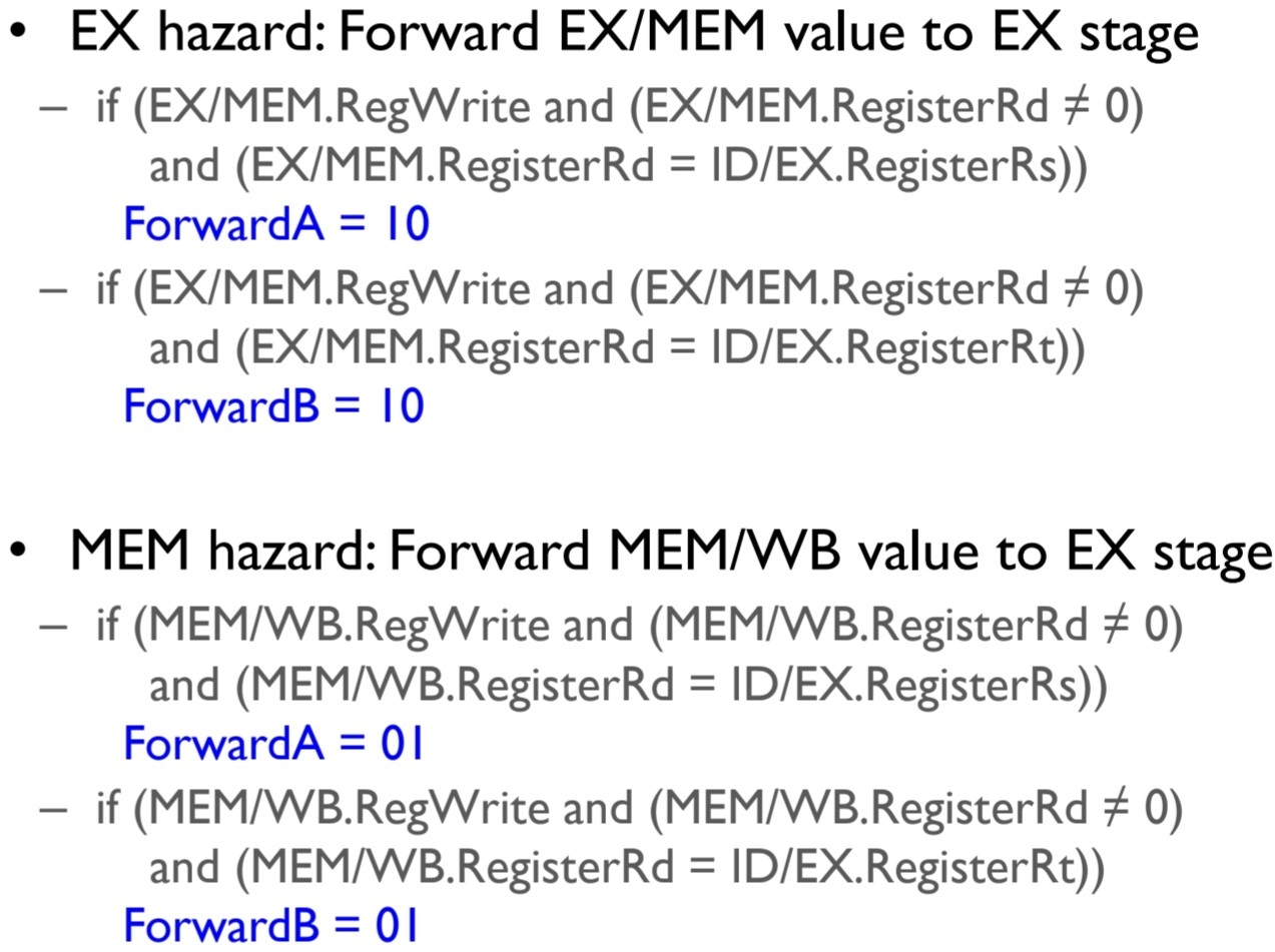
Then we may divide the cases as follows:
| case | condition | action |
|---|---|---|
| 1a. | EX/MEM.RegWrite == 1 && EX/MEM.Rd == ID/EX.Rs and not $zero | pass EX/MEM.rd memory to next cycle’s EX’s rs data location. |
| 1b. | EX/MEM.RegWrite == 1 && EX/MEM.Rd == ID/EX.Rt and not $zero | pass EX/MEM.rd memory to next cycle’s EX’s rt data location. |
| 2a. | MEM/WB.RegWrite == 1 && MEM/WB.Rd == ID/EX.Rs and not $zero | pass MEM/WB.rd memory to next cycle’s EX’s rs data location. |
| 2b. | MEM/WB.RegWrite == 1 && MEM/WB.Rd == ID/EX.Rt and not $zero | pass MEM/WB.rd memory to next cycle’s EX’s rt data location. |
And the implementation of the action can be achieved as follows:
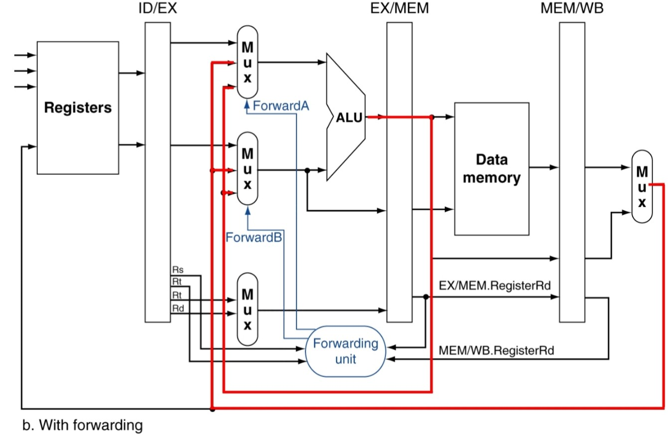
Now, consider a double data hazard as illustrated here.
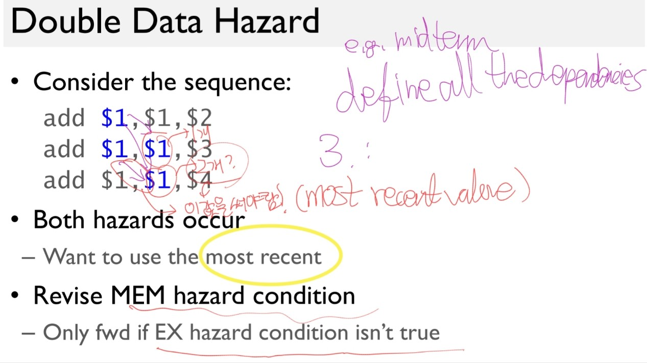
We have 3 WAR dependencies here.
However it suffices to address just two adjacent WARs: 1-2 and 2-3
as we only want to use the most recent data.
So we add a condition to the MEM hazard that no forwarding from EX/MEM to EX stage occur.
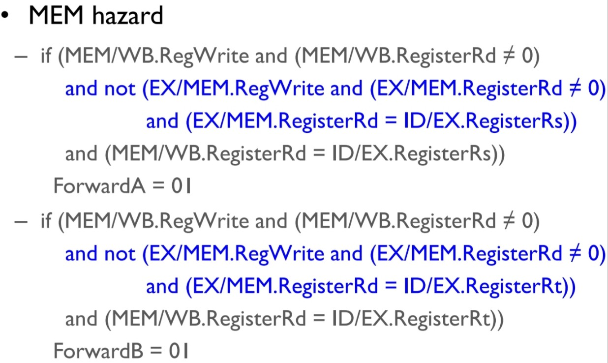
This is the final condition of the R-type Data dependency.
| case | condition | action |
|---|---|---|
| 1a. | EX/MEM.RegWrite == 1 && EX/MEM.Rd == ID/EX.Rs and not $zero | pass EX/MEM.rd memory to next cycle’s EX’s rs data location. |
| 1b. | EX/MEM.RegWrite == 1 && EX/MEM.Rd == ID/EX.Rt and not $zero | pass EX/MEM.rd memory to next cycle’s EX’s rt data location. |
| 2a. | 1a. not occured && MEM/WB.RegWrite == 1 && MEM/WB.Rd == ID/EX.Rs and not $zero | pass MEM/WB.rd memory to next cycle’s EX’s rs data location. |
| 2b. | 2a. not occured && MEM/WB.RegWrite == 1 && MEM/WB.Rd == ID/EX.Rt and not $zero | pass MEM/WB.rd memory to next cycle’s EX’s rt data location. |
fig 4.56
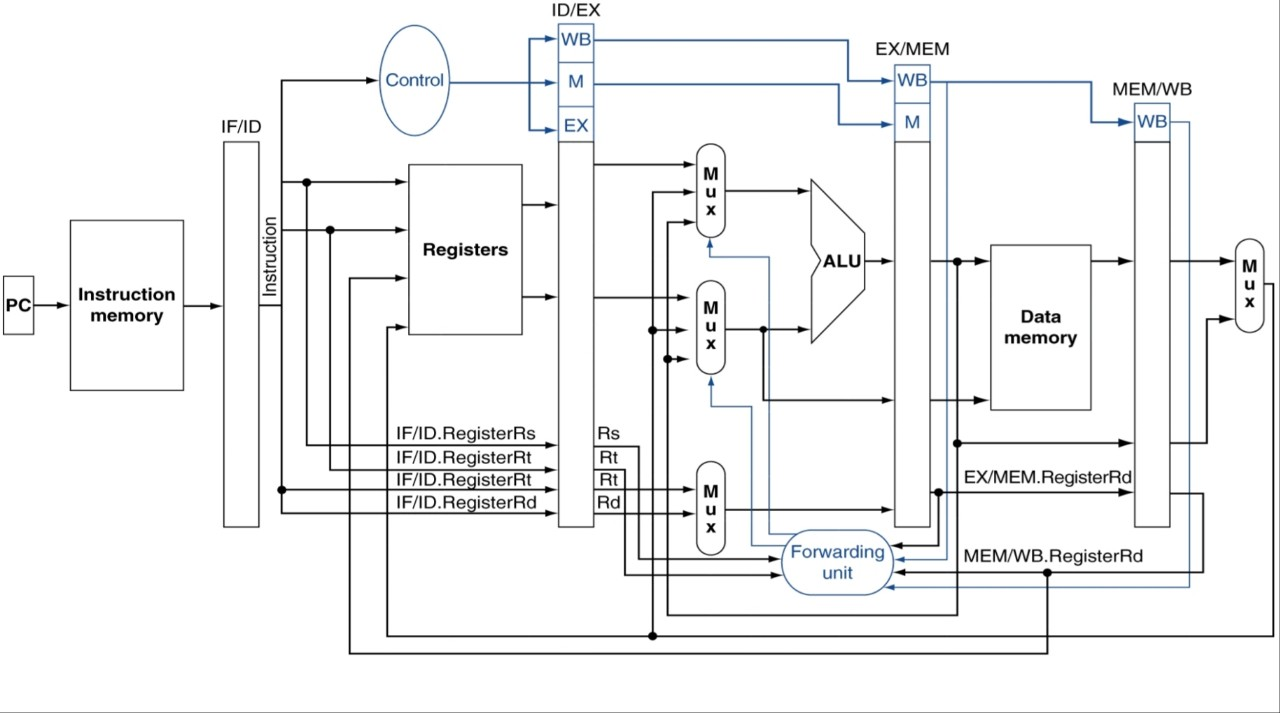
fig 4.53 등 보기
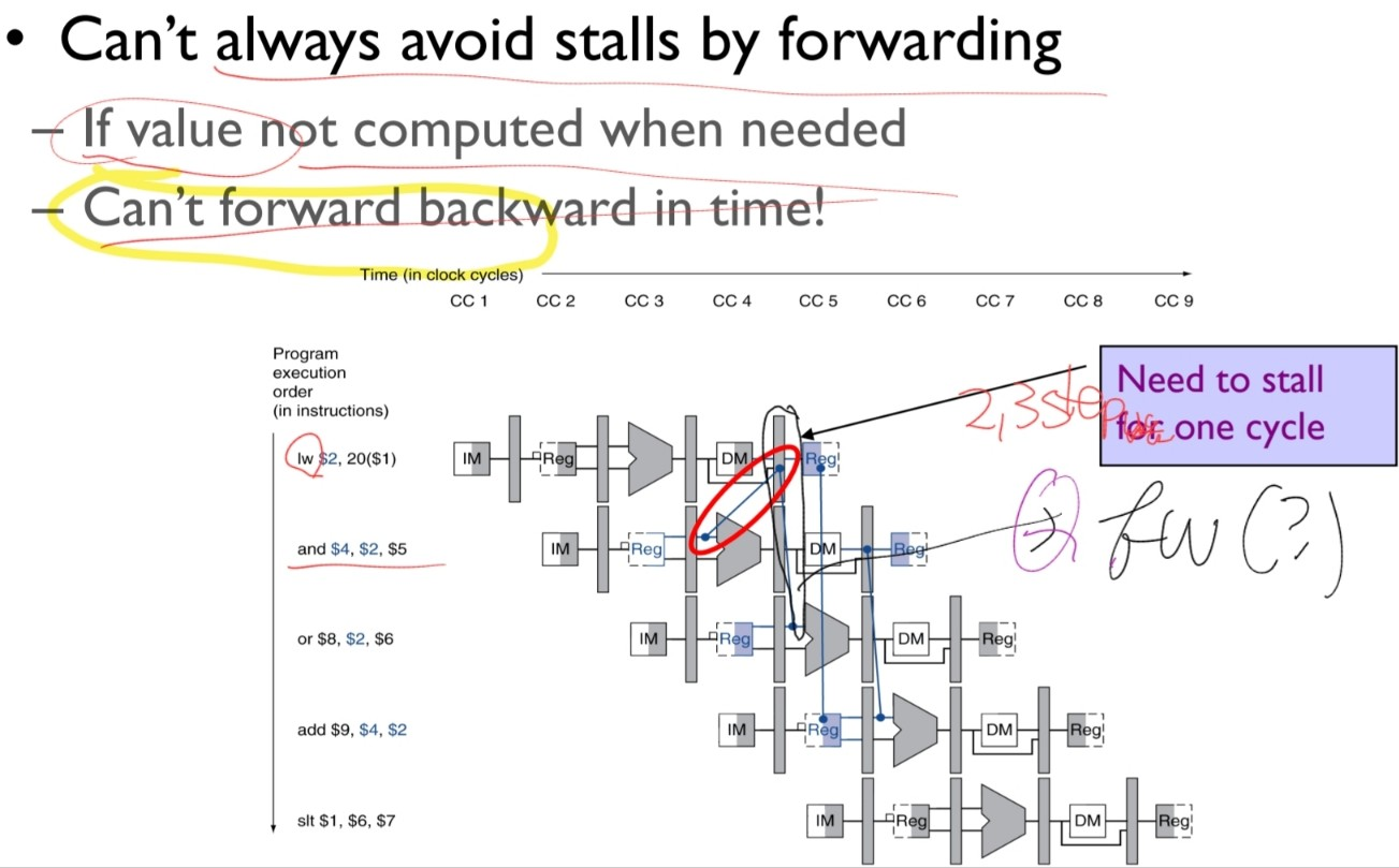
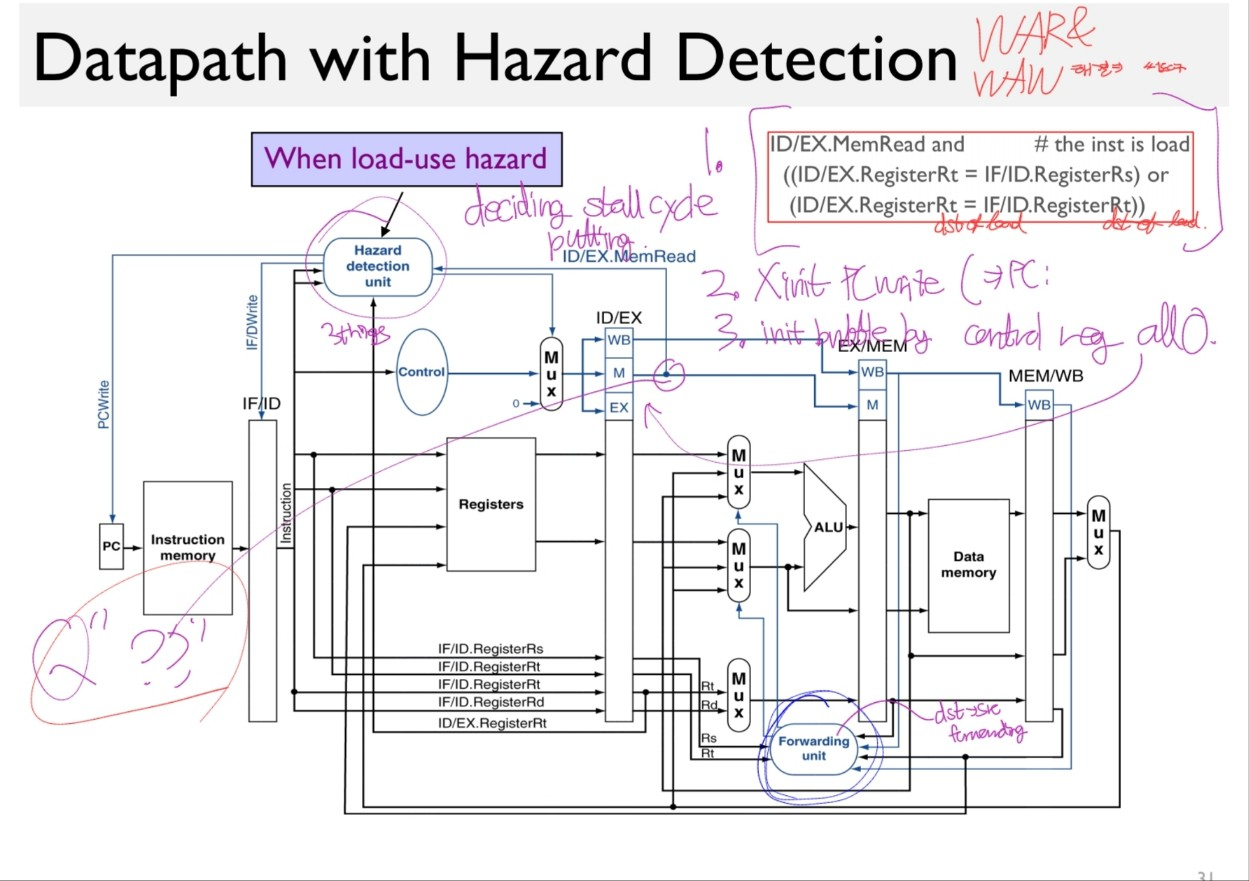
4.8.2. Load-Use data hazard
During R-type instruction execution, the data was retrieved at the end of the EX stage by the ALU.
So that we could pass the data without any stalling to the next instruction.
Loading the data, however, the first time we ever get the data is after the MEM stage, reading the memory.
Using the naive approach, we need 3 stalls.
Even if we use forwarding, a stall inevitably occur.
Let’s look at the detection, action & implementation, and the resultant pipeline.
Detection
detection condition:
- load instruction occur
- the load instruction is writing to the register($rt) that is used in later instructions.
if(
  ID/EX.MemRead == 1 # ONLY load instruction has that
  && (
    ID/EX.Rt == IF/ID.Rs ||
    ID/EX.Rt == IF/ID.Rt
  )
) then stall and forward!
in multiple hazards, we also use the most recent instructions’.
If you think of it, the dependency occurs 1 instruction before.
The R-a types occur 1 instruction before too. Thus they cannot occur simultaneously. X have to consider.
The R-b types occur 2 instruction before. Thus they may occur simultaneously, and the load-use hazard has the priority on forwarding.
As its detection for a certain instruction must happen 1 cycle in advance of R-types. (as IF/ID occur prior to ID/EX stage.)
Implementation
Pipeline Diagram
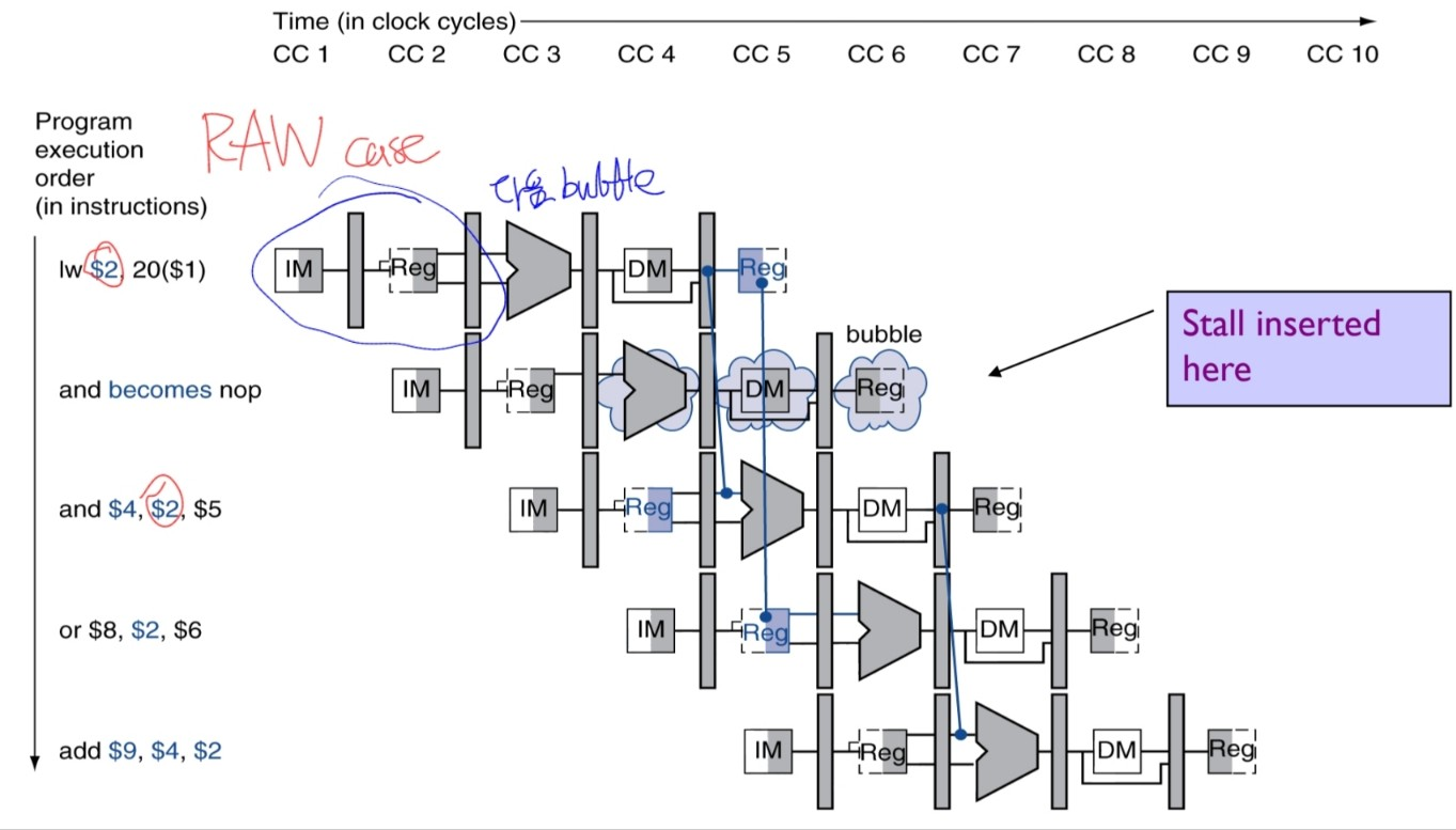
Or more accurately, with 2 differences,
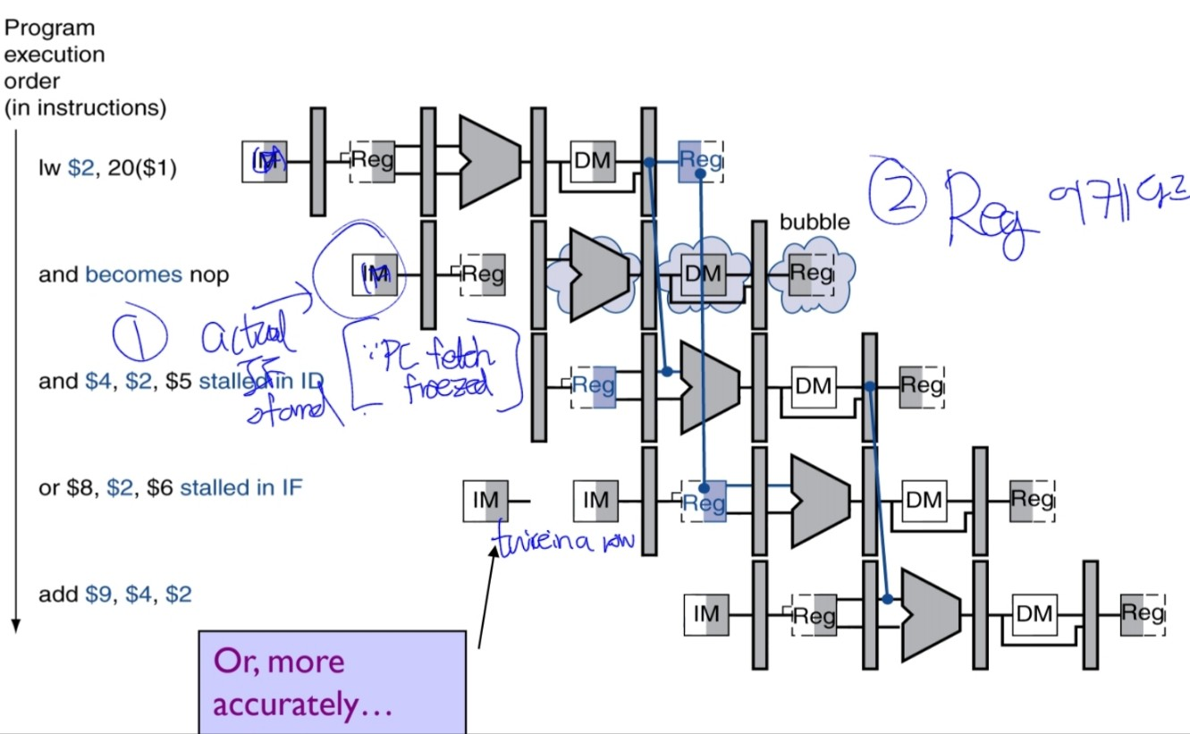
- The next instruction of the RAW-later instruction is fetched once again. we can achieve it by NOT updating the PC value.
- Send a nop instruction and before that, add the reg-and forward it at the CC5.
Recall from 4.8,
- nop: An instruction that does no operation to change state.
Resultant Datapath
4.9. Control Hazards
terms:
- flush: To discard instructions in a pipeline, usually due to an unexpected event.
- dynamic branch prediction: Prediction of branches at runtime using runtime information.
- branch prediction (= branch history table): A small memory that is indexed by the lower portion of the address of the branch instruction and that contains one or more bits indicating whether the branch was recently taken or not.
-
branch delay slot?: The slot directly after a delayed branch instruction, which in the MIPS architecture is filled by an instruction that does not affect the branch.
- branch target buffer: A structure that caches the destination PC or destination instruction for a branch. It is usually organized as a cache with tags, making it more costly than a simple prediction buffer.
- correlating predictor: A branch predictor that combines local behavior of a particular branch and global information about the behavior of some recent number of executed branches.
- tournament branch predictor: A branch predictor with multiple predictions for each branch and a selection mechanism that chooses which predictor to enable for a given branch.
4.10. Exceptions
terms:
- exception (= interrupt): An unscheduled event that disrupts program execution; used to detect overflow.
- interrupt: An exception that comes from outside of the processor. (Some architectures use the term interrupt for all exceptions.)
- vectored interrupt: An interrupt for which the address to which control is transferred is determined by the cause of the exception.
- imprecise interrupt (=imprecise exception): Interrupts or exceptions in pipelined computers that are not associated with the exact instruction that was the cause of the interrupt or exception.
- precise interrupt/exception: An interrupt or exception that is always associated with the correct instruction in pipelined computers.
4.11 Parallelism via Instructions
terms:
- instruction-level parallelism: The parallelism among instructions.
- multiple issue: A scheme whereby multiple instructions are launched in one clock cycle.
- static multiple issue: An approach to implementing a multiple-issue processor where many decisions are made by the compiler before execution.
- issue slots: The positions from which instructions cloud(발행하다) issue in a given clock cycle; by analogy, these correspond to positions at the starting blocks for a sprint.
- speculation: An approach whereby the compiler or processor guesses the outcome of an instruction to remove it as a dependence in executing other instructions.
- issue packet: The set of instructions that issues together in one clock cycle; the packet may be dtermined statically by the compiler or dynamically by the processor.
- Very Long Instruction Word (VLIW): A style of instruction set architecture that launches many operations that are defined to be independent in a single wide instruction, typically with many separate opcode fields.
- use latency: Number of clock cycles between a load instruction and an instruction that can use the result of the load without stalling th pipeline.
- loop unrolling
- register renaming
-
- antidependence (=name dependence)
-
- superscalar
- An advanced pipelining technique that enables the processor to execute more than one instruction per clock cycle by selecting them during execution.
-
- dynamic pipeline scheduling
- Hardware support for reordering the order of instruction execution so as to avoid stalls.
-
- commit unit
- The unit in a dynamic or out-of-order execution pipeline that decides when it is safe to release the result of an operation to programmer-visible registers and memory.
-
- reservation station
- A buffr within a functional unit that holds the operands and the operation.
-
- reorder buffer
- The buffer that holds results in a dynamically scheduled processor until it is safe to store the results to memory or a register.
-
- out-of-order execution
- A situation in pipelined execution whn an instruction blockd from executing dos not cause the following instructions to wait.
-
- in-order commit
- A commit in which the results of pipelined execution are written to the programmer visible state in the same order that instructions are fetched.
WAW, WAR dependencies: “false” dependencies.
4.16 Concluding Remarks
- instruction latency: The inherent execution time for an instruction.
.png)